Snell’s window and the external efficiency of light emitting diodes

This is a picture taken underwater looking up at the sky and it shows the Snell’s window effect. The Snell’s window is the bright central region of the photograph- it is quite a well-known phenomenon and the dark region at the edge of the photograph is sometimes called Snell’s blanket and that’s when the angle of incidence of the light on the surface of the water is such that no light penetrates the water. It is related to the critical angle for total internal reflection. An easier way to understand this problem is to envisage a point source of light at a depth z in the water -so this inverts the problem but that is ok because the laws of optics are reversible.
The inverted problem about how light escapes from a high refractive index material to a low refractive index material is related to the extraction efficiency of light emitting diodes (LEDs) – in the LED the light is generated inside a semiconductor typically with a refractive index, n1~3.5, and has to escape from the semiconductor into the air with n2=1.0003. Extraction efficiencies can be low because of the large refractive index of semiconductors.
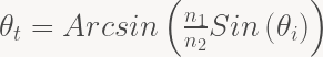
The amount of reflection and transmission at a surface is governed by Fresnel equations. The input parameters into Fresnel equations are the angle of incidence, the refractive index of media and the polarisation of the light. The other consideration is Snell law that gives the relationship between the angle of incidence and the angle of transmission (or refraction) and from Snell’s law, the critical angle for total internal reflection can be determined.
The photograph was taken with a surface between the water and the air which was not perfectly smooth there are ripples on the surface of the water. But to apply Fresnel’s equation to get an insight into the physics behind Snell’s window we are going to assume a perfectly smooth surface. Further in the photograph, we are looking up at the sun and the rays of light are coming in from a particular direction – in our modelling we are going to assume that the light is coming with equal probability from all directions in the celestial hemisphere. The kind of condition approximately by a very cloudy sky what I am going to call a Lambertian sky.
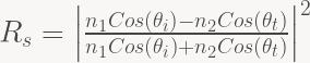
So Fresnel equations, give the fraction of light reflected at a surface between to media with refractive index 


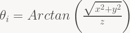
So to explain the Snell’s window in the photo we need to take account of the fact that the angle incidence at the surface (the x-y plane) for a viewer from a depth of z is given by :-
To help visualise the Snell’s window we can use the density plot function in Mathematica and we code the above equations to get the following :-

This for unpolarised light (an average of s and p polarized light) looking up from a depth of 5 meters (the x and y scales are in metres) the refractive index of the water is n1=1.33 and air n2 =1.00 – we assume a perfectly flat surface and light coming from all -directions with a Lambertian sky. It sort of captures the essence of the Snell’s window effect – although it might be more appropriate to call this the Fresnel’s window. Brewster’s angle is the angle at which p polarised light is transmitted with zero loss – there is no equivalent for s -polarised light and it means that under the sea the light is partially polarised.
If you would like to play around with different refractive indices and depths then check out the Snell’s Window simulation So the different refractive indices are appropriate to figuring out the extraction efficiency from LEDs and indeed the injection efficiency into solar cells.
Below is a movie of how Snell’s window at the surface changes as depth increases – it assumes n1=1.33 the refractive index of water:-
The movie below shows how Snell’s window at the surface changes as the refractive index n1 increases – so that it shows how less light escapes from the material as the refractive index increases – it relates to how light escapes from an LED – the depth is 4 microns and the x-y scale is in microns.

Thanks for your link to a Snell window simulator and your article & videos. I find the principles involved very interesting and am curious of the lack of data in certain useful applications or as an aid in modeling other areas of science. Wish I would’ve known about NOAA before my attempt at the Marines, I didn’t learn about most of it until recently. My mom’s fear of me always choosing the bottom of the pool to play would’ve proven useful in the least.
What kind of changes would be involved if the LED was submerged in a cryofluid with the temperature past its lambda point to become a superfluid?